Wall
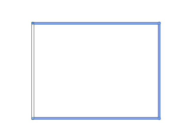
Draw Rectangular wall
Wall is a non-structural member in the building design.
Step-1
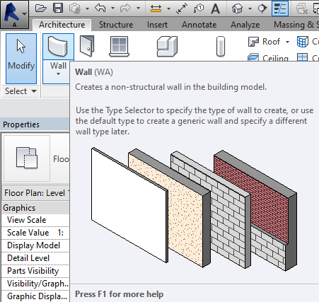
-Select wall or type WA to create walls
Step-2
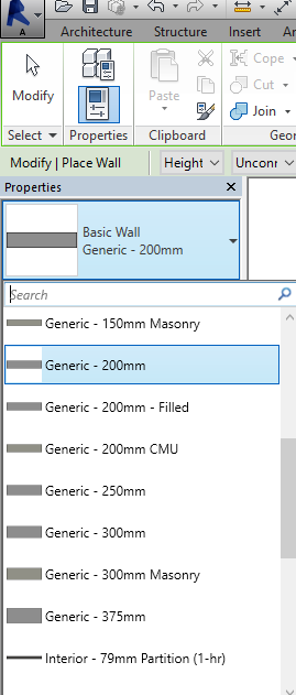
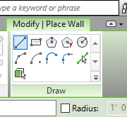
-You can select different types of walls as per your choice as shown in the above figure.
Step-3
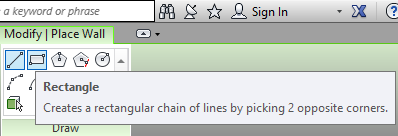
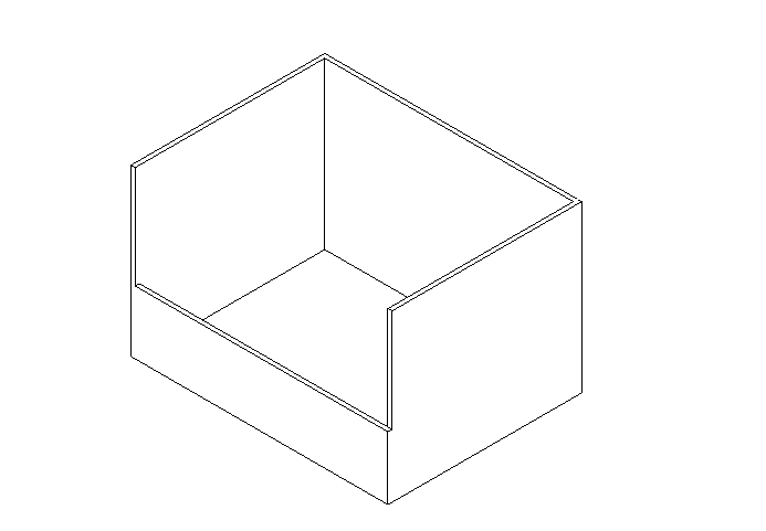
-you can draw different shapes of the wall. For now, I prefer a rectangle to draw the exterior walls as well as boundaries or compound walls.
Step-4
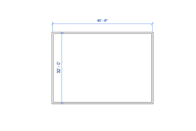
-just click and drag and again click to create a rectangular wall or any other shape.
Set dimension
Step-1
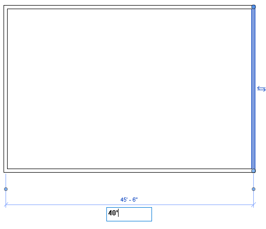
-Click on the adjacent wall to customize or to check the dimension of the wall and double-click on the given dimension or distance to change its length or you can use the keyboard arrow keys to move objects.
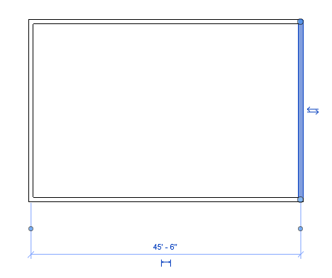
Step-2
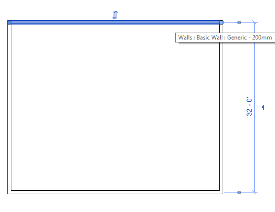

-similarly, click on another adjacent side to customize another wall dimension.
Edit wall type
-You can edit or customize a wall or any other elements in edit type
Step-1
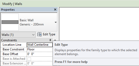
-In the properties panel you can ‘Edit type’ click on that to edit walls or elements.
Step-2
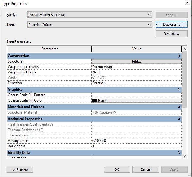
-Click on ‘Duplicate’ to create a duplicate type. Duplicates are created because while you are editing on a particular wall or element the other elements will not be disturbed.
or
-Duplicate types are created because other walls or elements should not be disturbed while you are editing a specific or particular wall.
Step-3
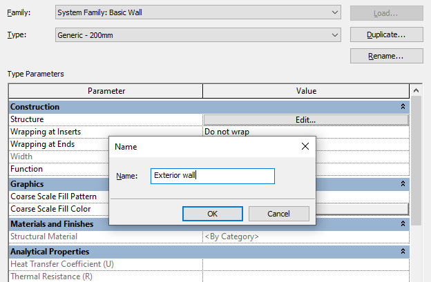
-you can rename the wall types as you wish. choose or select names wisely so that you can identify easily.
Step-4
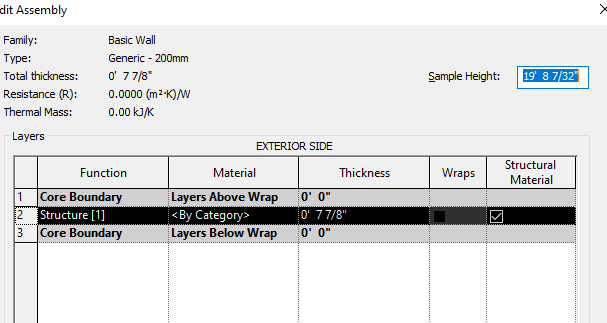
-you will see an Edit Assembly dialogue box from that yu can edit thickness of the wall which you have selected.
Step-5
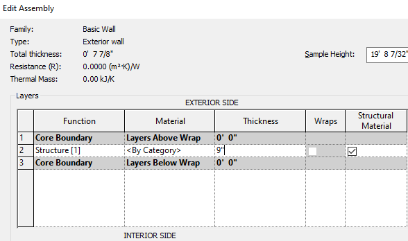
-Click on that to change the thickness of the wall.
Step-6
-You can select multiple walls to edit.
Step-7
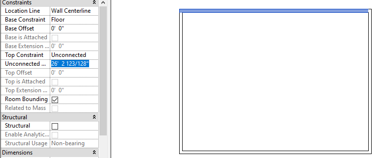
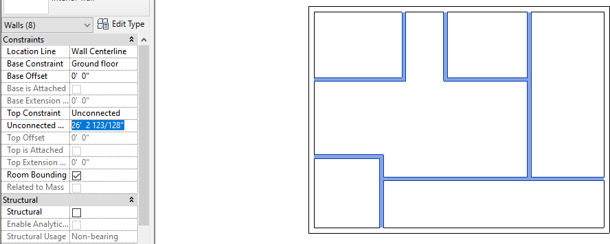
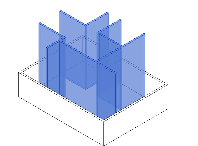
-Reduce the height of the wall to the proper level of your slab by selecting it (you can select multiple walls) and mentioning it as shown in the figure.
-If you do not reduce the height then it will overlap with the slab and pass-through it.
-open a 3D view to check the height of the wall.
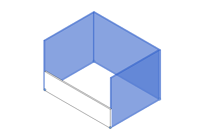
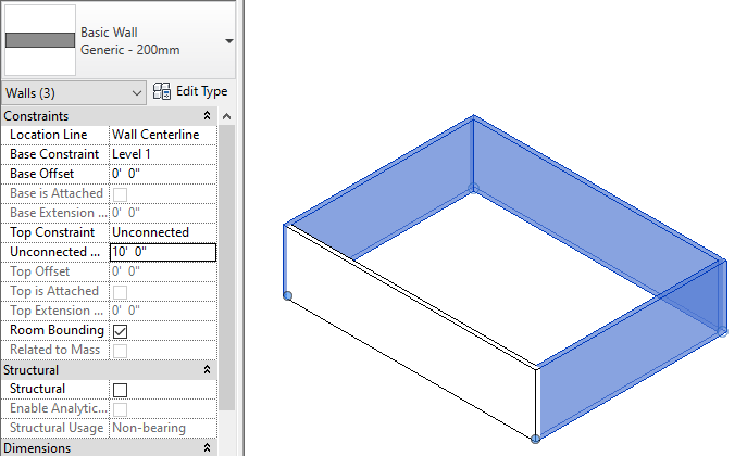
-Select Multiple walls and reduce it to 10′(10 feet) or up to the level of your height.
Draw Straight wall or Interior wall
Step-1
-Similarly, select a line to draw a single wall as a partition wall
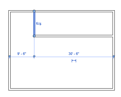
Step-2
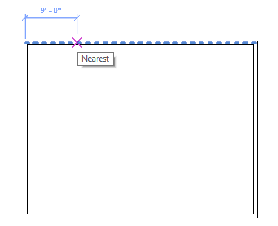
-You can see here if you move the cursor, the distance will appear with a mark or identifying symbol due to snapping was enable.
Step-3
-Click and drag to draw a line.
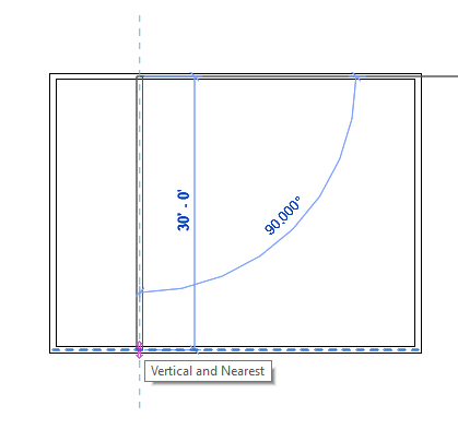
Step-4
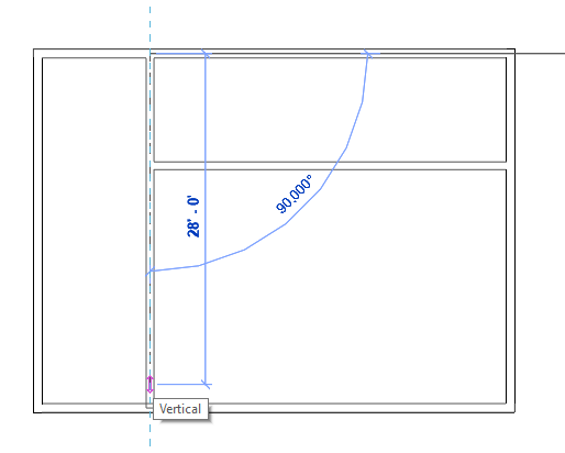
-Due to snapping it will show the midpoint mark. Click and drag to create another line.
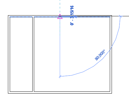
Step-5
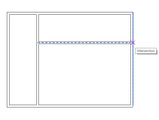
-Draw a perpendicular line as another partition wall.
Step-6
-if you want to remove the extra line then don’t panic, click at the end of the line and just pull or drag to reduce its length. You can see here the line has been reduced.
The next step is to change its thickness.
Step-7
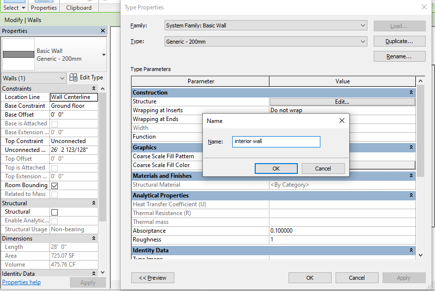
-Create a duplicate wall type to edit interior walls and reduce its thickness as we done before to the exterior wall.
Step-8
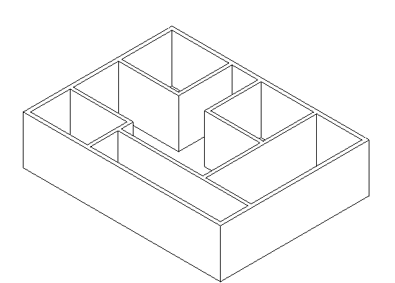
-Similarly, select a wall (you can multiple walls) to reduce the height of the wall to the proper level.
-as you can see below fig the height of the wall is reduced.
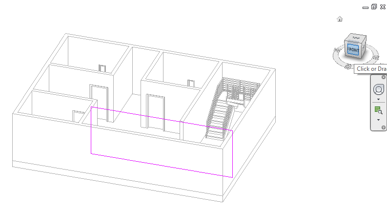
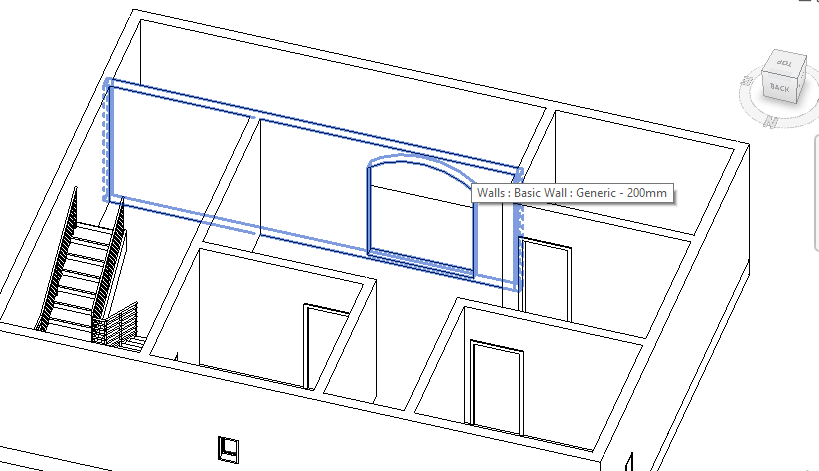
Edit Profile for wall
You can change the shapes of the wall and you can make openings to the wall. Follow the steps as shown below to edit wall profile.
Step-1
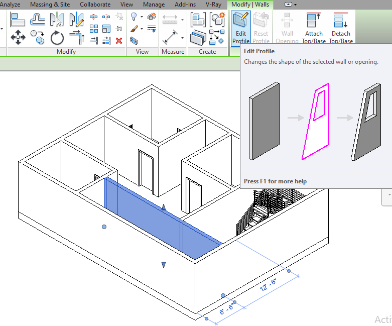
-Select the wall and click on edit profile to enter ‘Sketch mode’
*Later ill show you how to design a staircase.
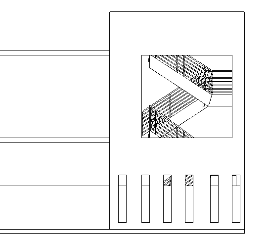
Step-2
-Select any elevation view so that you can modify easily.
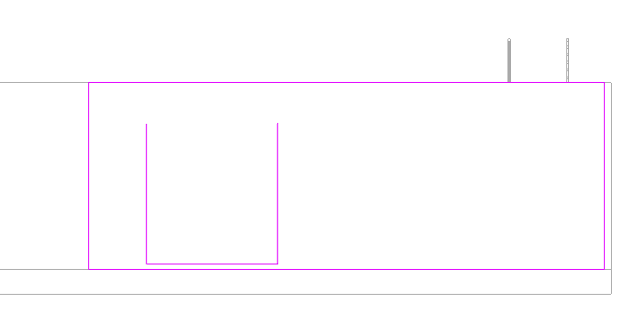
Step-3
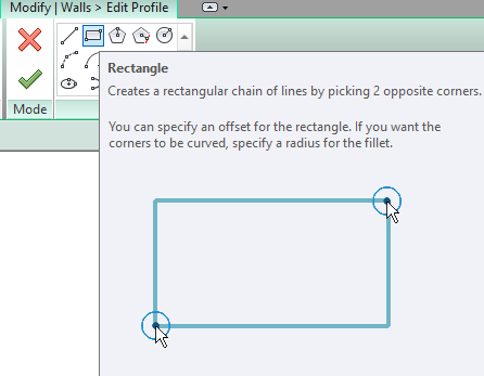
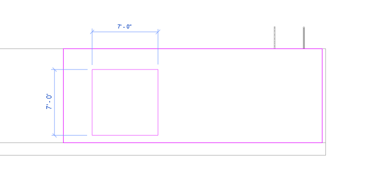
-Go to draw panels and select shapes to modify.
-in this ill show you using Rectangle. Draw a rectangle on the selected wall.
*You can click Finish Edit Mode to make a rectangle opening.
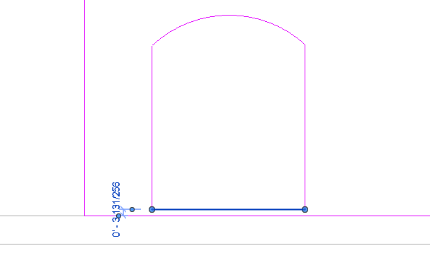
Step-4
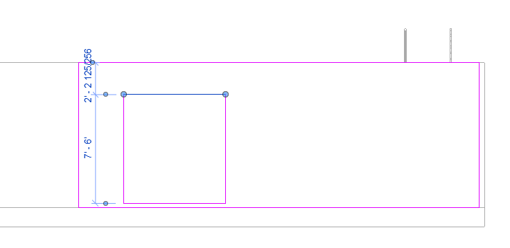
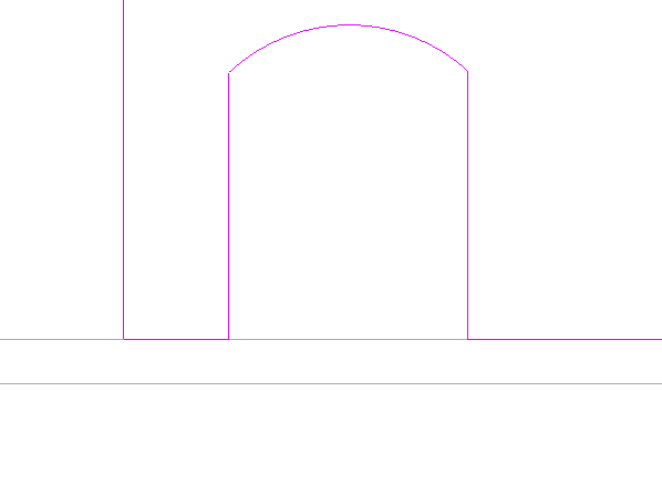
-Select the line and delete to draw an arc.
Step-5
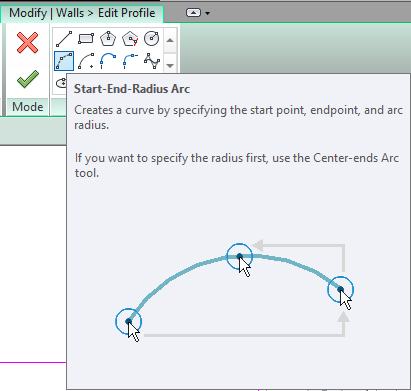
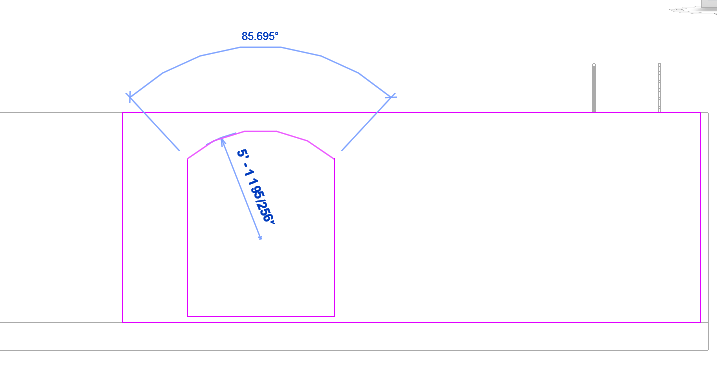
-Select Start-End-Radius to draw an arc.
Step-6
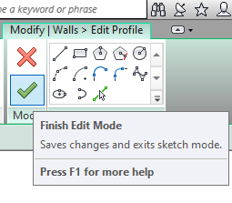
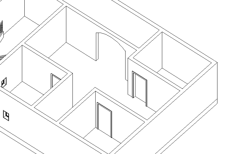
-Click on Finish Edit mode and change view to see the modified wall.
-you can create openings in the elevation wall.
Creating Mid-End faces
Step-1
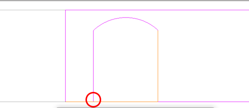
-if you delete the line and intersect the lines with each other then an error will occur as shown below.
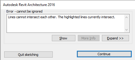
-If this box appears then click on ‘continue’ and make changes to the wall.
Step-2
-Reduce or cut the line using split.
Step-3
-Change its view to see the modified wall.
Floor
The inside lower horizontal surface of a room, hall, or any other structure.
Step-1
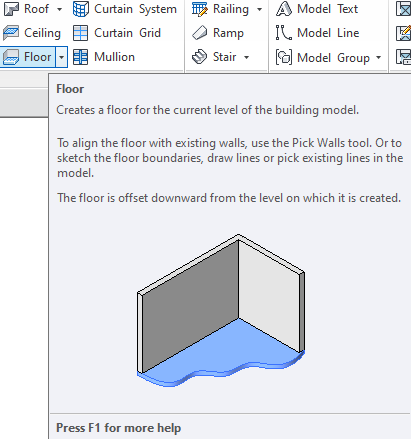
-It creates a floor at the selected level. it creates using drawing tools such as line, rectangle, and more.
Step-2
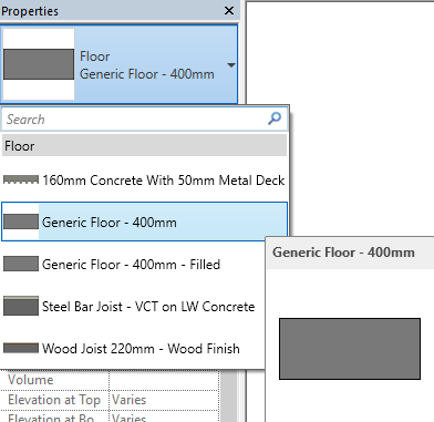
-From the properties panel, you can choose different types of floors.
Step-3
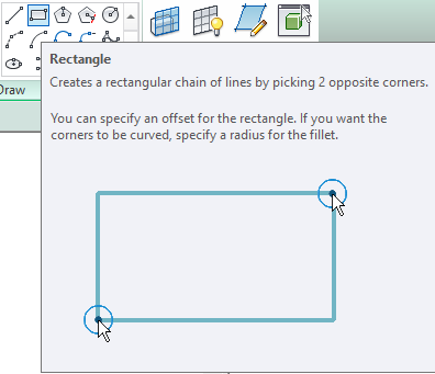
-From the Draw panel select shape(s) to create a floor design.
Draw a Floor design
Step-1
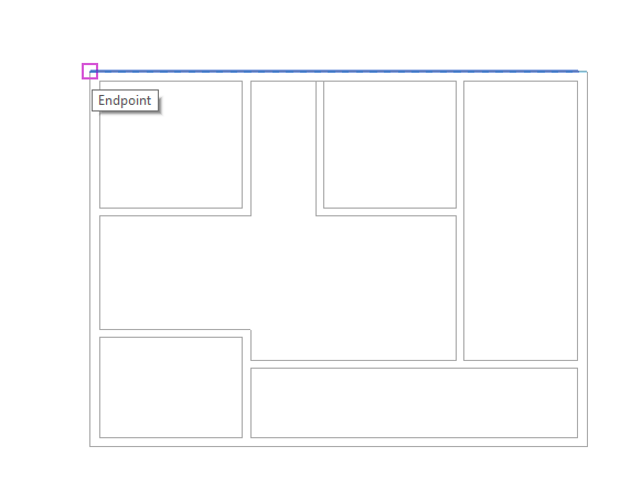

-keep the cursor at one end and click and drag towards another end to create a floor.
Step-2
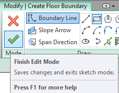
-If you have done with editing then Click on finish edit mode which is in the form of a tick mark.
Edit Boundaries For floor
If you want to edit floor size then follow these steps.
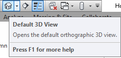
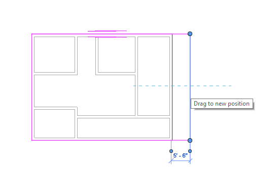
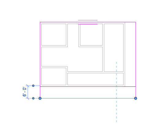
-First click on 3D view as shown in figure-1
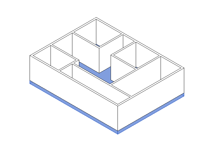
-Select floor which you want to edit as shown in figure-2
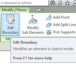
-Click on Edit boundaries to modify or edit as shown in figure-3
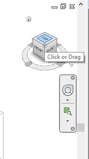
-Click on the top view in the ViewCube(as shown in fig-4), so that you can edit boundaries easily.
-Click on the line and drag towards any direction as per your need or you can use keyboard arrow keys to move as shown in fig-5.
Edit Floor type
Step-1
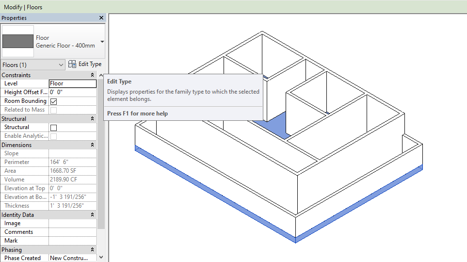
-To edit the floor thickness first select floor and then click on edit type.
Step-2
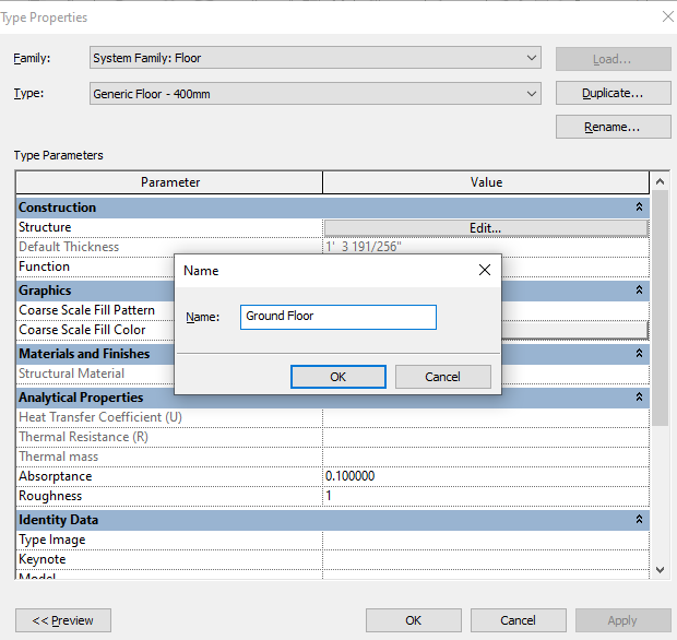
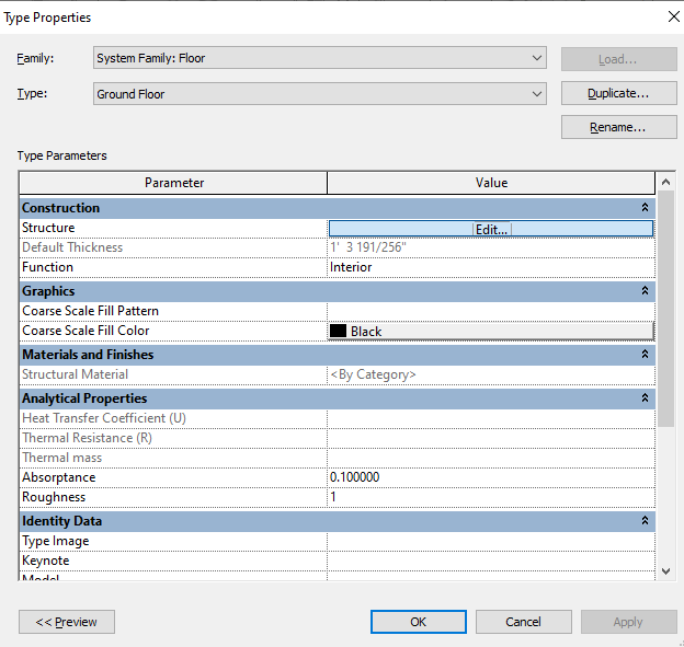
-create a duplicate name for this as we have done before to the wall as shown. Click on edit to modify its thickness.
Step-3
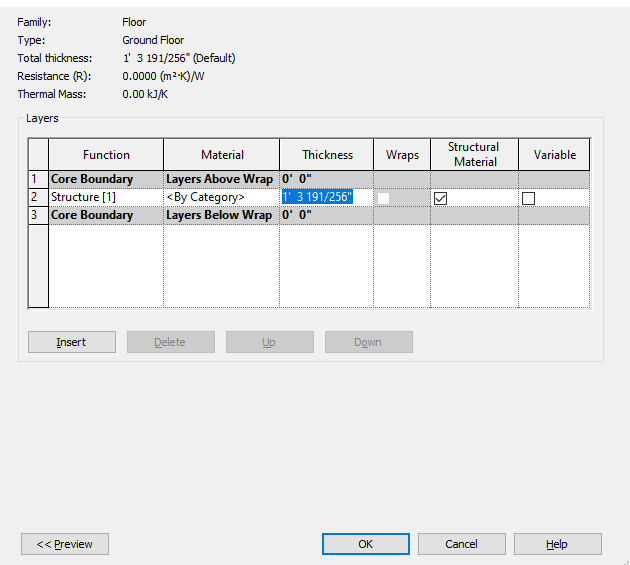
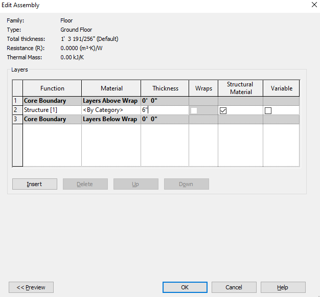
-Select a default value and change its thickness. (I prefer 6″ or 6 inches).
Roof
A structure which is covering a building from the top and supported on the walls of the building.
Step-1
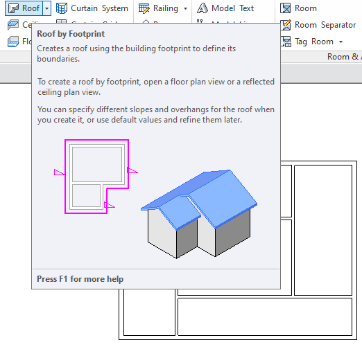
-To Create a flat roof or sloped roof select room from the ribbons tab or panel.
Step-2
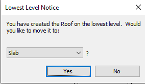
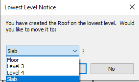
-Next pop-up will appear like this click ‘yes’ to continue if you created only two levels.
-If you have created more than two levels then you have to mention that on which level you want to create/design a roof.
Step-3
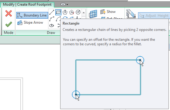
-Select a shape that you want to draw or create a roof.
Step-4
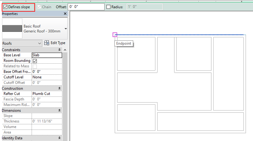
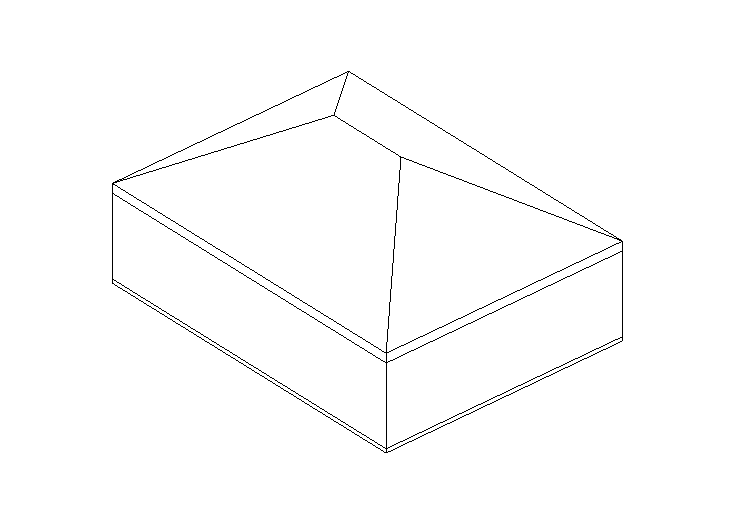
-If you have selected a ‘Defines slopes’ (as shown in fig) then your roof will be in sloped form.
Step-5
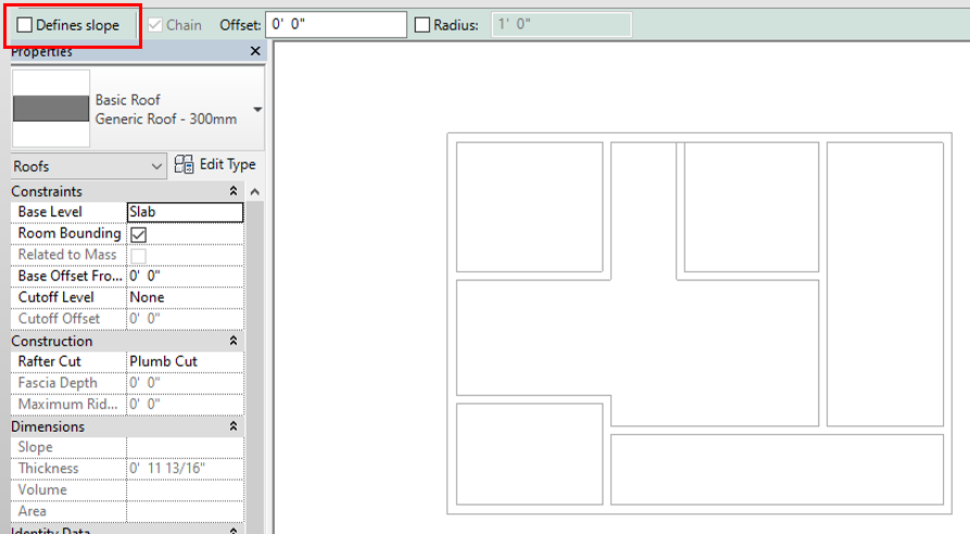
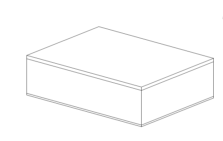
-If you don’t want a sloped roof then un-tick the ‘defines slopes’ option.
Edit Roof Type
Step-1
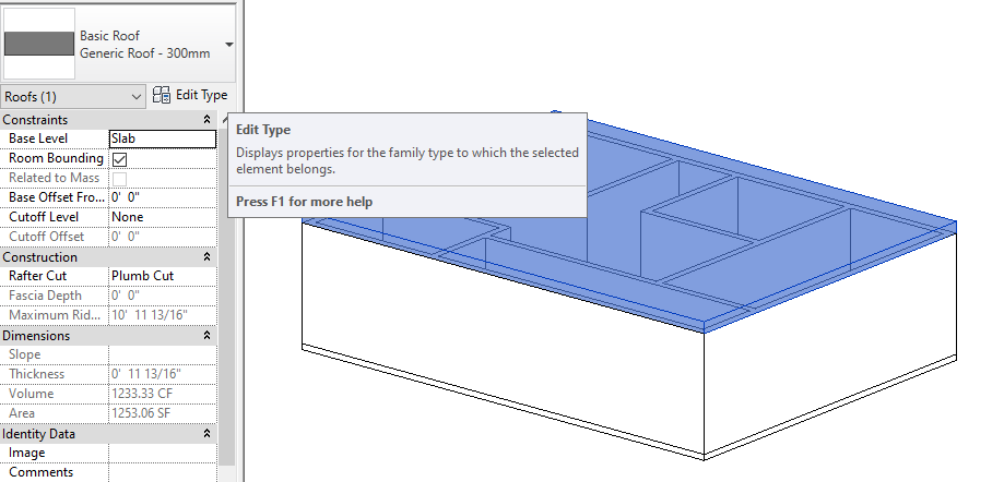
-First select roof and click ‘Edit type’ to edit
Step-2
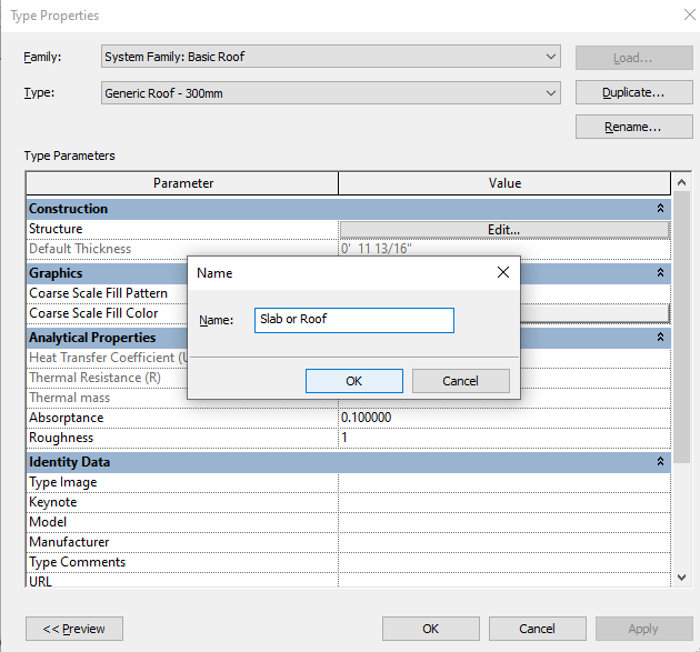
-Create a Duplicate type and rename it so that you can identify easily.
-if you create a Duplicate then other slabs that are/that will be created on the other levels will not be disturbed.
Step-3
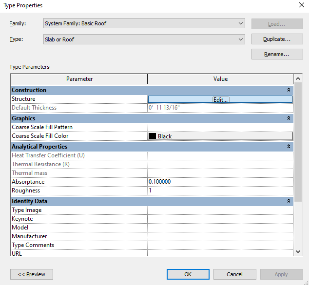
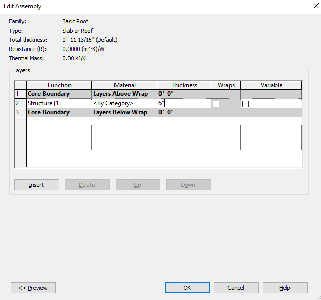
-Click on edit and change its default thickness to 6″ (6 inches). If you want then you can change it as per your requirements.
Edit Footprint for Roof
You can Edit the Roof and you can change its shape and dimension. Follow the steps as shown below to edit the Roof.
Step-1
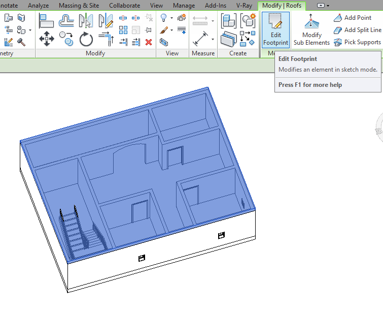
-It will be better if the view is in a 3D view. Select the roof and click on Edit footprint to enter ‘Sketch mode’ as shown in fig.
Step-2
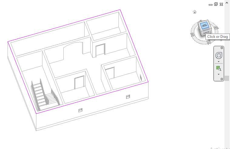
-The Roof which you want to Edit will highlight with pink lines or borders as ‘Sketch Mode’ so that you can identify easily.
-Click on Top view as shown in Fig so that you can edit easily.
Step-3
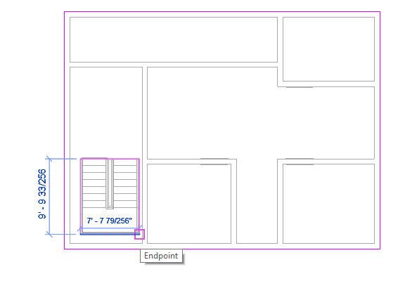
-Select Rectangle and draw to edit the footprint on the slab.
Step-4
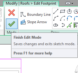
-Click on finish edit mode
Step-5
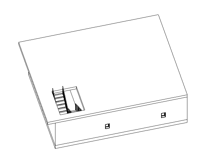
-change its view so you can see this clearly.
Doors
-It is a hinged barrier that provides privacy and security by controlling access to the entranceway of a building or room by closing or opening.
Place a Door
Step-1
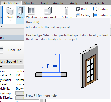
-select a door to add to the building or to the room.
Step-2
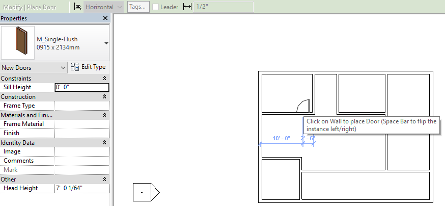
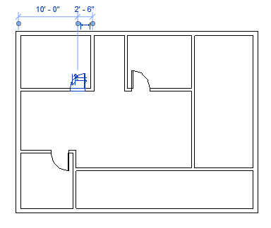
-when the door is selected it automatically gets along with the cursor, just keep the cursor on the wall and click on it
Step-3
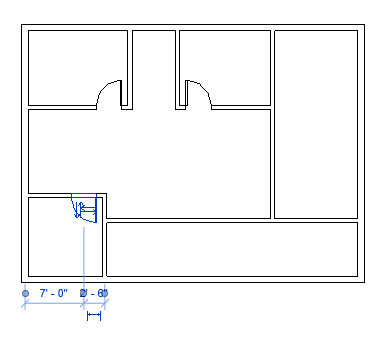
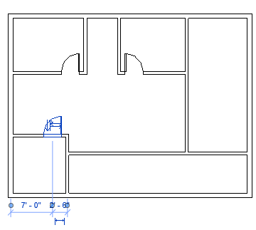
-After placing all the doors and if you want to change its position then select that door and hit ‘spacebar’.
Step-4
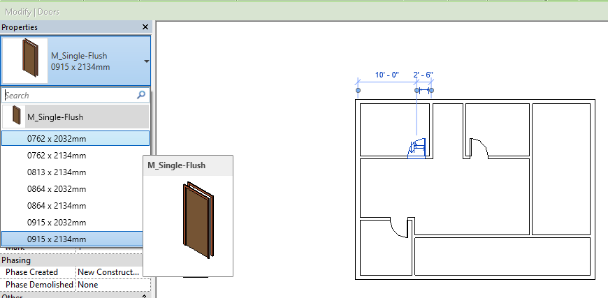
-You can change or replace the doors by choosing different sizes in properties.
-Select the door which you want to replace and select the different shapes(as shown in fig) as per your requirements.
Edit Door
Step-1
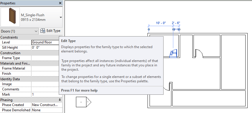
-Select the door which you want to edit and click on edit type.
Step-2

-You can edit the thickness, height, width, trim projection exterior, trim projection interior, trim width of the selected door in the dimension box as shown in fig.
-First create a duplicate type and rename it.
-Click on the default values and change them as per your requirements.
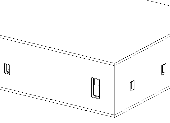
Window
Windows are used in walls and the purpose is for allowing air, light, ventilation, and will exhaust humidity.
Place a window
Step-1
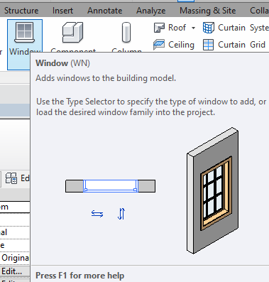
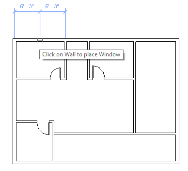
-select the window from ribbon panel. you will get it along with cursor, keep the cursor on the wall to keep place a window.
Step-2
-After placing a window and want to change its direction select that window and hit ‘spacebar’ to change its direction.
-if you want to change windows position then you can use ‘keyboard arrow keys’ or use mouse.
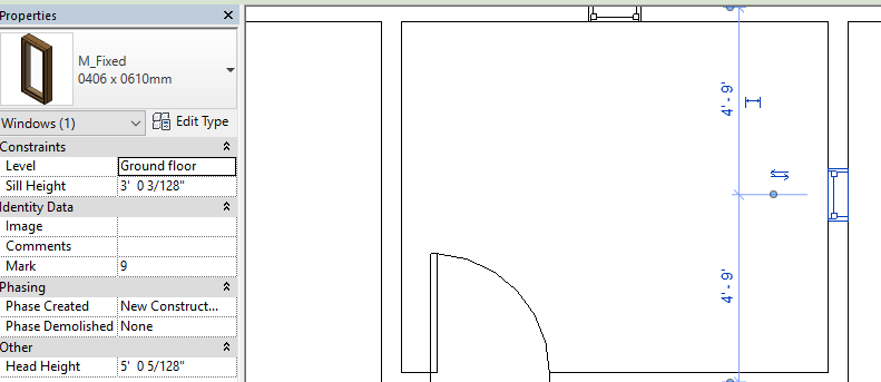
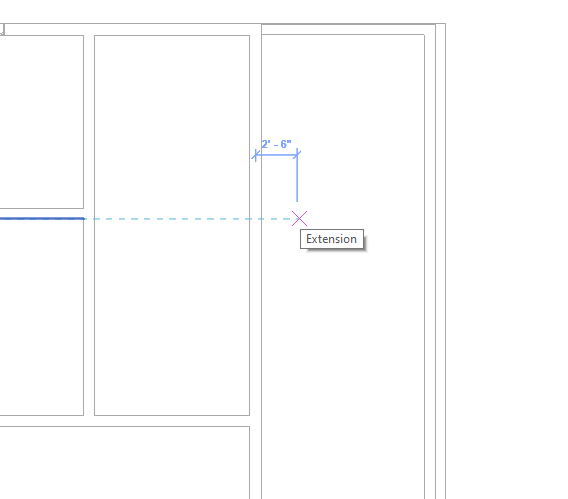
Change windows size and position
-You can change its size and position in 3D view.
Step-1
-select a window that you want to make changes and edit its default dimension length.
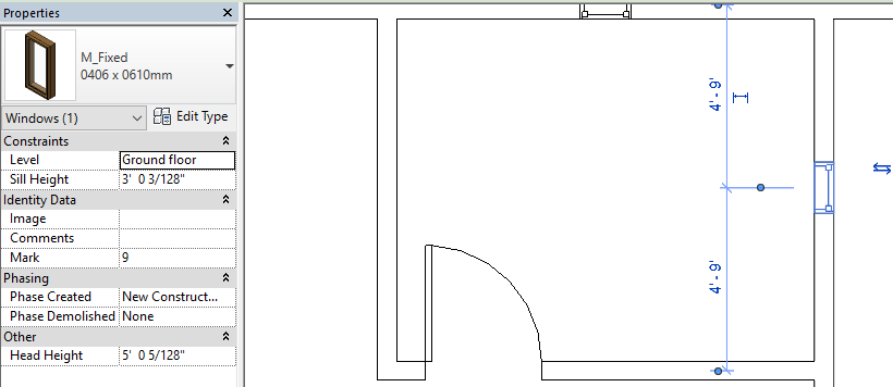
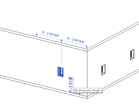
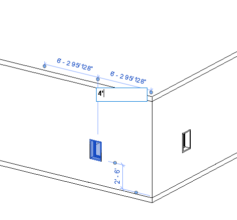
Step-2
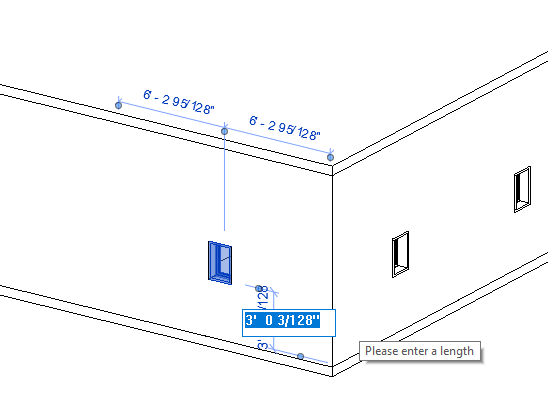
–Click on that and change its value or length.
Step-3
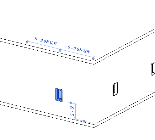
-you can change its direction towards either horizontal or vertical.
Step-4
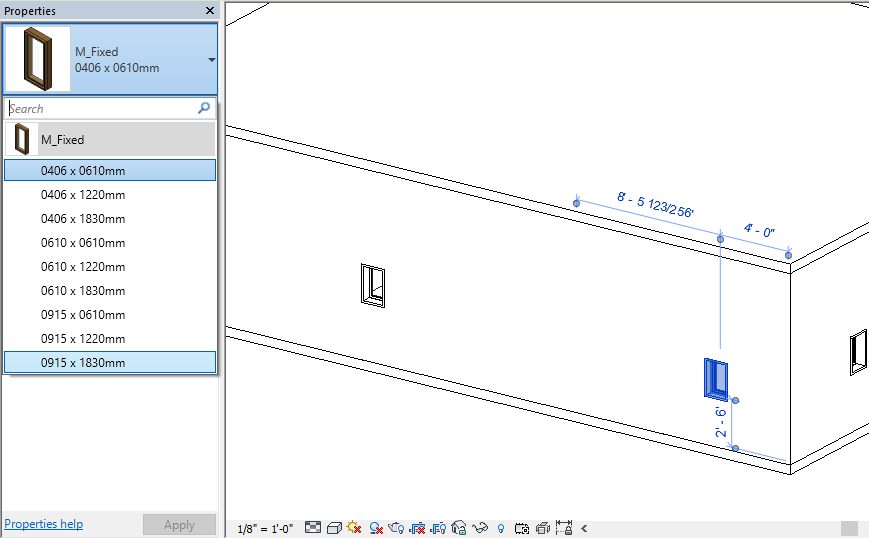
-select a window which you want to edit and choose sizes from the properties panel to change its size as shown in fig.
Sairs
-A set of steps or a flight leading from one floor to another floor.
Create a staircase
Step-1
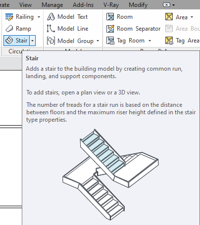
-Select stairs from the ribbon tab to draw a staircase.
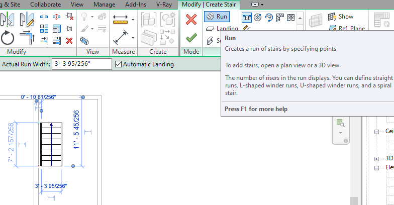
Step-2
-Keep the cursor and click and drag towards any direction from where you want to start stairs, and click again to complete one side/direction.
Step-3
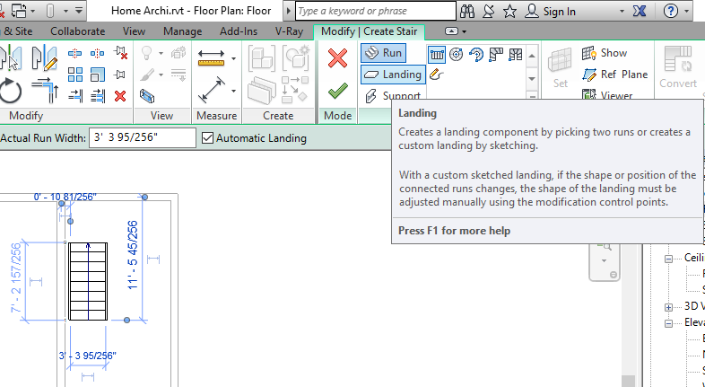
-After completion of one side, click on Landing soon after click Run to create a Landing as shown below.
Step-4
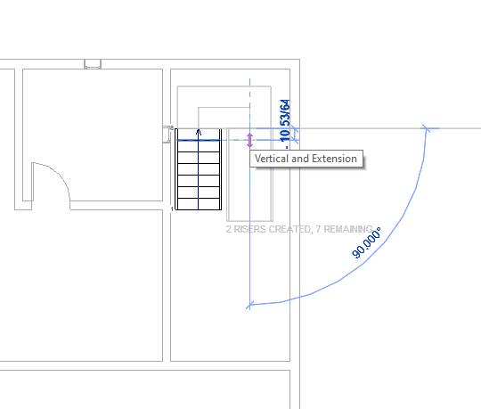
-As you can see here when you keep the cursor on the other side or beside it, landing appears automatically, click and drag to create the other side of the stair.
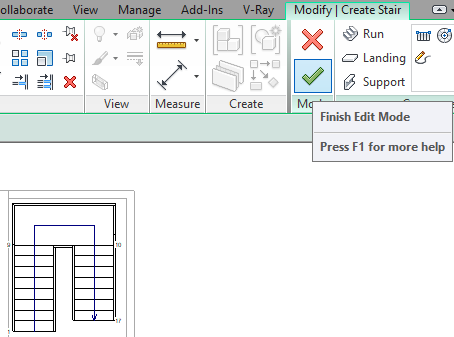
-Click on Finish edit mode to completion.
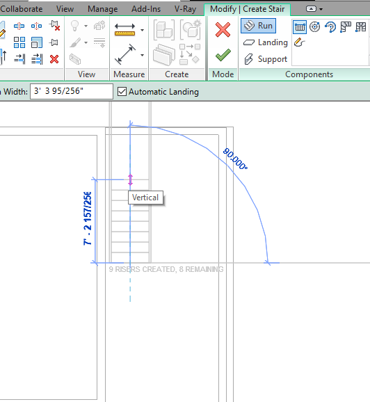
Edit Staircase
Step-1
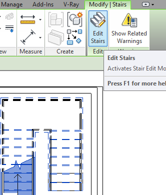
-Select stairs and click on edit stairs as shown in fig.
Step-2
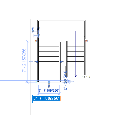
-Click on any one side of the stair and you will see a default width dimension. click and change it as per your requirements.
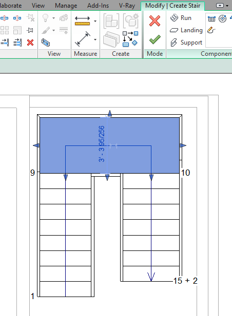
-Similarly, you can change the landing size.
Step-3
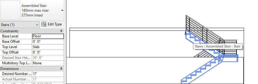
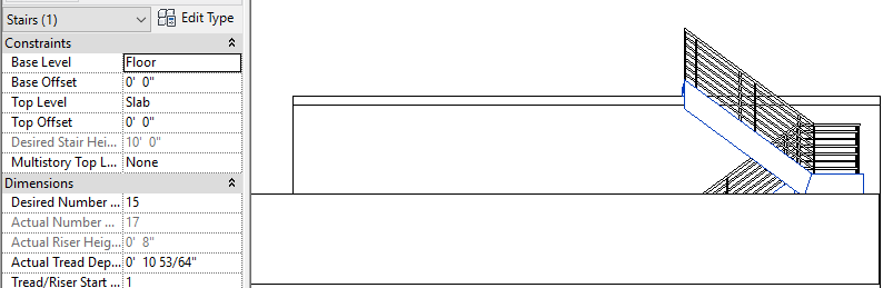
-If the height of the stair is below the slab then select a stair and change the desired number of steps so that it can reach the level of the slab.
Step-4
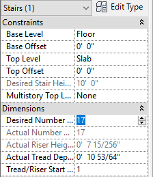
-change desired numbers and hit enter and then click ok.
Step-5
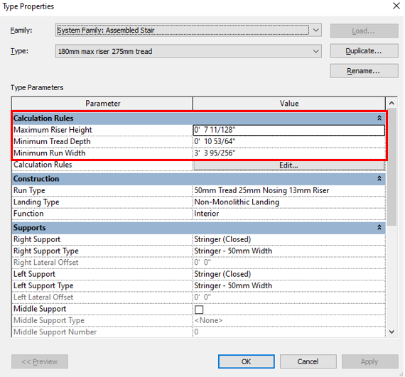
-To change the RIser height, Tread depth. and width of the stair then select stair and click ‘Edit type’ in the properties panel and change its default values as per your requirements.
Create a Stairs By Sketch
-You can Sketch stairs and railing as you wish.
Step-1
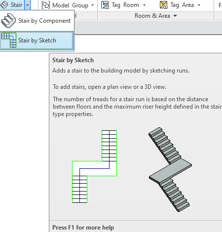
-Select stairs and choose a stair by sketch.
Step-2
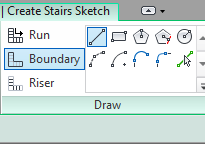
-select a boundary as a Railing and select a line from the draw panel.
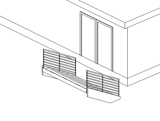
Step-3
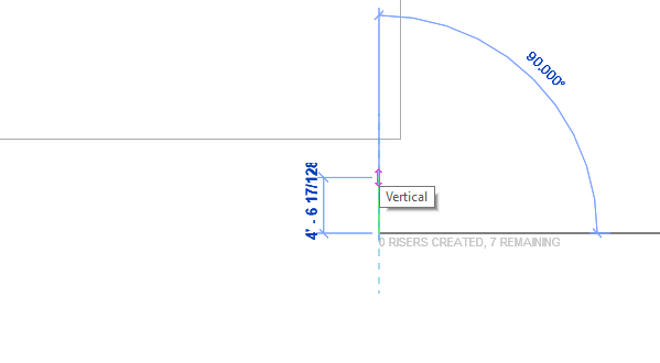
-Draw the lines towards the wall not from the wall as shown in fig. If you have drawn lines from the wall then your stairs will be reversible.
Step-4
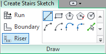
-Select riser as steps. you can choose any shapes based on the boundaries you have drawn.
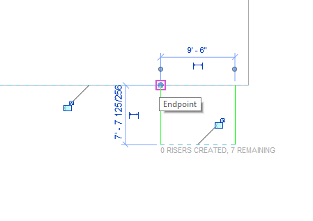
Step-5
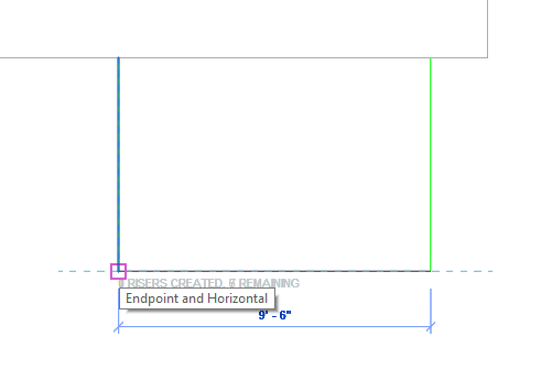
-Draw a line to connect two boundaries.
Step-6
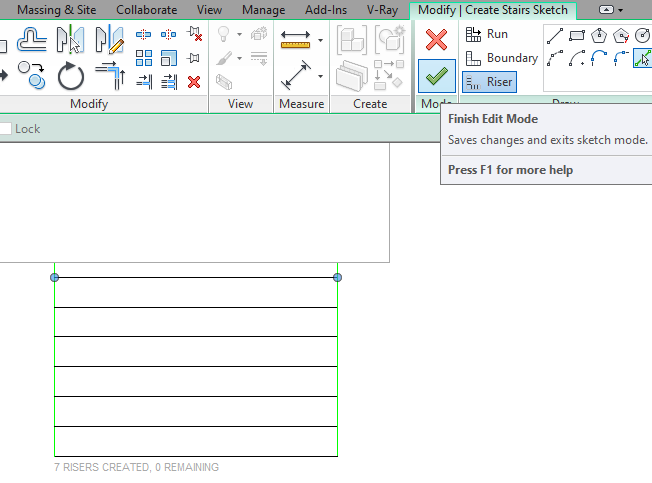
_Click on Finish Edit mode to complete the design.
Step-7
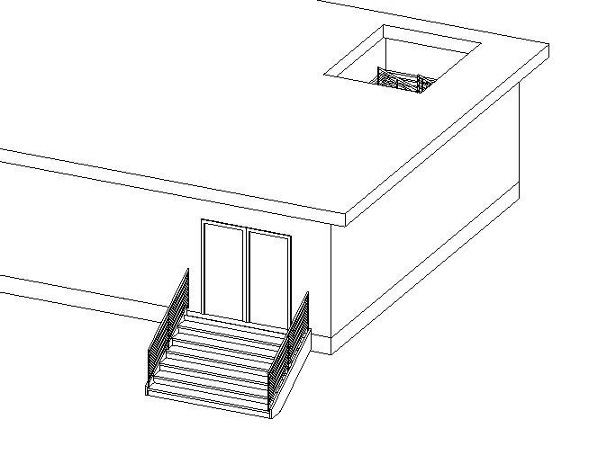
-Change the view to see the designed stairs.
Step-9

-If your stairs are reversible then go to plan view and click on the arrow(as shown in fig) to change its direction.
Edit Railings
Step-1
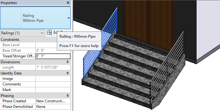
-Select railing and select railing dialogue from the properties panel.
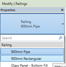
-Choose railing types from the list and select any one type to change its style.
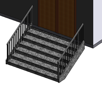
-you can see the final form of railing after changing or replacing its style.
Build another Floor
If you want to create the same floor plan on another level then follow these steps as shown below.
Step-1
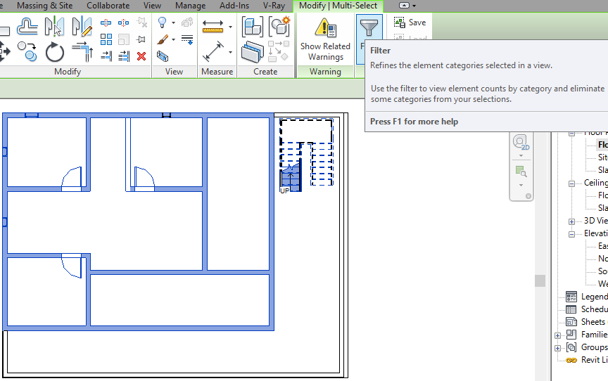
-Select the elements that you want to create on another level and click on ‘Filter’ to refine.
Step-2
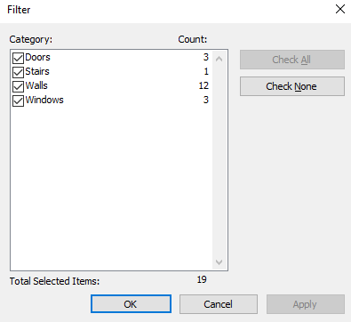
-The dialogue box will appear like this. select or tick on the elements that you want to copy.
-you can untick the elements that you don’t want to copy/filter.
Step-3
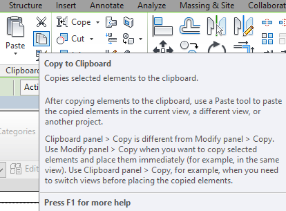
-Click on ‘copy to clipboard’ so that selected elements will be copied.
Step-4
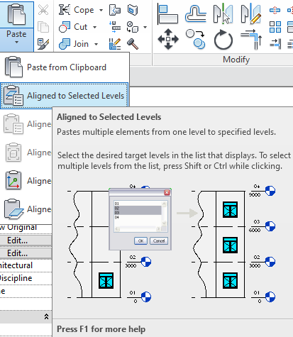
-Go to paste and choose ‘Aligned to selected levels’ so that copied elements will be paste or align.
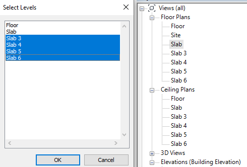
Step-5
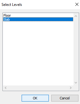
-In the Next step Select or click on which level you want to align or paste the elements.
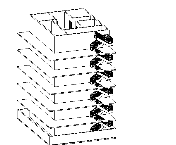
Step-6
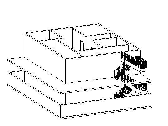
-Click 3D view to see the aligned elements on specified levels.
See the below image as an example. If you create and select more levels you can align more.